How It Works
Quick Summary
This site is generated by a Python CLI that reads Structurizr DSL and produces an MkDocs Material site. Architecture changes follow Git workflow: branch, edit, validate, review, merge, deploy.
The Workflow
flowchart LR
    A[Create Branch] --> B[Edit DSL / Docs]
    B --> C[Validate Locally]
    C --> D[Pull Request]
    D --> E[Peer Review]
    E --> F[Merge to Main]
    F --> G[Auto-Deploy Site]
What Powers This Site
The DSL Behind It
Here is the Player Performance system -- first the generated container diagram, then the DSL that produced it:
softwareSystemPlayerPerformance = softwareSystem "Player Performance" "Training analytics, GPS tracking, and match statistics" {

    containerPlayerPerformanceDatabase = container "Performance Database" "Training sessions, GPS data, match statistics, and fitness scores" "PostgreSQL" "DATASET" {
    }

    containerPlayerPerformanceApi = container "Player Performance API" "Training data ingestion, analytics, and performance reporting" "Python" "SERVICE" {
        properties {
            "Repository" "https://dev.azure.com/BelFoot/_git/player-performance-api"
        }
        this -> containerPlayerPerformanceDatabase "Manage data" "SQL/TCP"
    }

    containerPlayerPerformanceDashboard = container "Performance Dashboard" "Visual analytics for player fitness, load management, and match performance" "Power BI" "DASHBOARD" {
        userHeadCoach -> this "Review player performance and set training plans"
        this -> containerPlayerPerformanceApi "Get performance data" "JSON/HTTPS"
    }
}
One block of DSL produces the diagram above and all associated pages -- automatically.
Everything on this site is generated from plain-text files stored in a single Git repository:
| File Type | Purpose |
|---|---|
workspace.dsl |
Defines all software systems, containers, relationships, and deployment infrastructure |
boundedContext.mmd |
Maps business domains to data entities and their relationships |
software-system-docs/**/0000-introduction.md |
Per-system documentation: description, business capabilities, business data |
workspace/pages/*.md |
Cross-cutting documentation pages (like this one) |
workspace/adrs/*.md |
Architecture Decision Records |
The structurizr-mkdocs CLI reads the source files and produces:
- C4 diagrams at every level (landscape, context, container, component, deployment, dynamic)
- Bounded context pages with entity relationship diagrams and cross-context links
- Business capability maps linking business capabilities to software systems
- Actor pages showing which systems each role interacts with
- Landscape overviews broken down by organizational group
- Deployment views per infrastructure zone
Before any change reaches production, the CI/CD pipeline checks:
- DSL syntax -- the Structurizr CLI validates the workspace compiles without errors
- Site generation -- the static site generator confirms all diagrams render and all links resolve
- Peer review -- an architect reviews the pull request for correctness and consistency
Technology Stack
| Layer | Tool | Role |
|---|---|---|
| Modeling | Structurizr DSL | Define architecture as code using the C4 model |
| Export | Structurizr vNext (Docker) | Export DSL to JSON + C4 PlantUML diagrams |
| Diagrams | PlantUML (Docker) | Render .puml files to clickable SVG diagrams |
| Generation | structurizr-mkdocs-generatr | Parse workspace, generate Markdown + MkDocs config (inspired by structurizr-site-generatr) |
| Site | MkDocs Material | Build the static site with Material theme |
| Governance | Git + Pull Requests | Track every change with full audit trail |
| AI | Claude Code | Automate system creation, audits, and documentation generation |
Tool Connectors
Architecture is most valuable when it flows into the tools your teams already use.
Built: Atlassian Compass
A production-grade connector syncs software system and container metadata from the Structurizr workspace to Atlassian Compass as components via GraphQL. Teams see architecture context -- descriptions, technology choices, relationships, repository links -- directly in their Compass catalog alongside CI/CD and incident data.
The connector supports full lifecycle management: create, update, and delete components; sync relationships and dependencies; and map team ownership automatically.
Roadmap
The following connectors are planned but not yet built:
- Backstage -- Export system and API definitions as Backstage catalog entities
- Port -- Publish architecture entities as Port blueprints
- Cloud drift detection -- Compare deployed Azure/AWS infrastructure against the architecture model
Writing Guide
When writing documentation pages for your architecture site, the following markup features are available.
C4 Diagram Embeds
Embed any diagram defined in the workspace using the embed: syntax. The view key matches the key defined in the Structurizr DSL views section. See the Structurizr documentation for details.
<div class="diagram-container"><button class="diagram-zoom-btn" title="Enlarge diagram" data-diagram-src="../diagrams/structurizr-SystemLandscapeUserCommunicationsManager.svg" data-diagram-title="Communications Manager"><svg xmlns="http://www.w3.org/2000/svg" viewBox="0 0 24 24" width="20" height="20" fill="currentColor"><path d="M15 3l2.3 2.3-2.89 2.87 1.42 1.42L18.7 6.7 21 9V3h-6zM3 9l2.3-2.3 2.87 2.89 1.42-1.42L6.7 5.3 9 3H3v6zm6 12l-2.3-2.3 2.89-2.87-1.42-1.42L5.3 17.3 3 15v6h6zm12-6l-2.3 2.3-2.87-2.89-1.42 1.42 2.89 2.87L15 21h6v-6z"/></svg></button><object data="../diagrams/structurizr-SystemLandscapeUserCommunicationsManager.svg" type="image/svg+xml" class="diagram">Communications Manager</object></div>
Mermaid Diagrams
Mermaid.js diagrams are supported natively by MkDocs Material:
PlantUML Diagrams
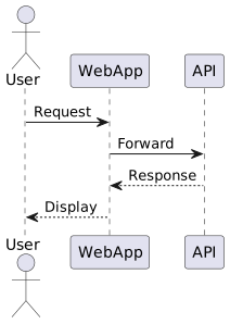
PlantUML can be embedded directly in Markdown and will be rendered as SVG:
Images
Place images in the assets directory and reference them with standard Markdown syntax:

Bring This to Your Organization
This framework can be set up for any enterprise -- from startups to large organizations with hundreds of software systems. Interested in what this could look like for your landscape? Get in touch.